Stress-Strain Curve
The stress-strain curve provides a way to read the static load capacity of materials. For many materials, including metals, the load-bearing capacity is one of the most important material properties. The load-bearing capacity of metals is tested with a so-called tensile test.
A standardised metal rod is slowly pulled apart until the rod breaks under the load. From the beginning of the tensile test until it breaks, the material under test behaves differently, which is shown in the stress-strain curve.
The elastic deformation limit, plastic deformation limit, maximum tensile strength and breaking limit can also be read off. These values are particularly important for designers, as they make it possible to find out how much force a material, in relation to the cross-section used, can absorb without permanently deforming.
The graph in the diagram shows how much the material stretches under the increasing stress. If you look more closely at the course of the curve, in most cases the behaviour of the material can be divided into four phases.
These are called:
- elastic deformation
- plastic deformation / flow region
- plastic deformation / strain hardening
- plastic deformation / reduction of area
The tensile test ends when the metal rod breaks.
This means that the material only returns to its original state in the area of the first phase, the elastic deformation, without deformation or damage, when the tensile force is reduced again. In the following phases the deformation is permanent and therefore irreversible.
The data of a stress-strain curve are reliable. However, the values given depend on a number of variables that directly influence the measurement results. These include the method of material production, material composition, microscopic imperfections and temperature. For this reason, the diagram of each tensile test is slightly different and several tensile tests are always necessary to produce a reliable stress-strain curve with the average values obtained.
The Interpretation
To fully understand this diagram, knowledge of some technical terms is of great importance. As described above, the stress-strain curve shows the mechanical properties of materials such as steel, rustproof steel or aluminium.
From the diagram it can be seen how much the material can stretch in relation to an increasing application of force.
In the diagram, the horizontal axis indicates the strain in percent. The stress is shown on the vertical axis. The graph is divided into four sections (A-D), of which the first section represents the elastic deformation.
In the remaining areas, only plastic deformation then takes place. However, the material behaves differently in each phase of plastic deformation. Area B defines the flow region.
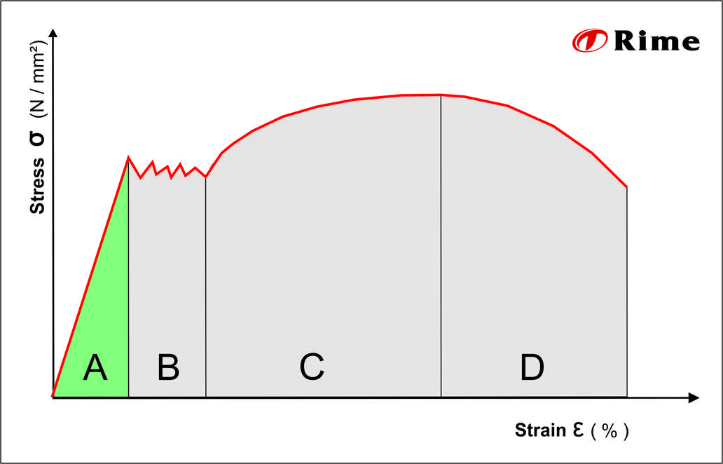
This is an area in which the material is strained beyond its elastic capacity and the first plastic deformations occur. In the flow region, the stress changes very irregularly with increasing strain, so that a wavy line is created in the curve. In section C, the stress continues to rise sharply, with plastic deformation also increasing. When the maximum load-bearing capacity is reached, the material begins necking in the cross-section. Reduction of area and the associated loss in material thickness leads to a further, rapid and progressive weakening of the material until the metal rod finally breaks.
The elastic deformation (A)
In the first phase of the stress-strain damage we speak of elastic deformation. As soon as the stress acting on the material is removed, the material shortens back to its original length. This is called complete recovery or resilience. The area of elastic deformation can in turn be divided into two phases. In the first phase the material stretches proportionally to the stress acting on it. This extension is also called linear-elastic or proportional deformation.
This behaviour of materials within the range of proportional deformation was described in 1668 by the English polymath Robert Hooke, in Hooke’s law named after him. The point at which the maximum linear-elastic elongation (strain) is reached is called the proportional limit. Beyond this limit elastic deformation still takes place, however, greater elongation occurs in this section under increasing applied force. The elongation or strain is therefore greater than the increasing stress.
The flow region (B)
A further, small increase in stress can be enough to cause the proportional limit to be exceeded. Under this force the material begins to flow and the first plastic deformation occurs. The area in which the material flows lies between the upper and lower flow limit. The highest flow point is the point accompanied by an initial, sudden loss of quality. As a result, the stress required to continue to elongate (strain) the material reduces immediately and reaches the lowest flow point.
After these points are exceeded the material has definitively deformed irreparably, even if the force were to be removed immediately. If the force continues to increase, the crystal defects (dislocations) start to wander and increase, which leads to further quality losses at the first flow point and stress and strain behave irregularly in relation to each other. This produces the characteristic, wavy curve section.
Material hardening (C)
If the stress is increased further, an increasing number of upright dislocations form in the crystal lattice, which prevent movement of the previous still sliding dislocations. At the same time, the stress in the crystal lattice continues to increase, which causes hardening of the material. This means that an increasingly larger force is required for further plastic deformation. However, this process cannot be continued infinitely. Each material has its specific maximum force.
Necking (D)
If the maximum force is exceeded the material begins to neck. In the crystal lattice of the metal bar so many dislocations have occurred that they can no longer lead to hardening but instead contribute to the formation of voids or cavities. Apart from necking, the voids also cause the material cross-section to reduce. The stress now acts on an increasingly smaller cross-section, which enhances this process still further.
As the tensile test continues the necking increases until the tapered cross-section can no longer withstand the stress. This is when the metal bar tears at the weakest point.
Using the stress-strain curve
The diagram or curve shows how materials behave under increasing force. In practice, the flow limit is one value, because from this point materials deform plastically. At Rime this value is very interesting, as this point enables the sheet panels to be formed by bending or roll bending. Especially in load-bearing constructions, attention must be paid on ensuring that the load never reaches the flow limit, so that no unwanted deformation occurs.
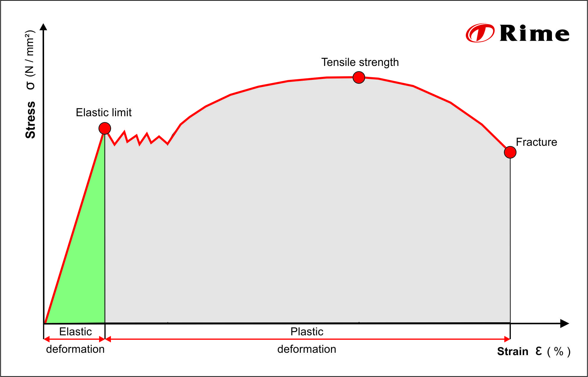
Elastic limit
At the start of a tensile test, stress and strain are proportional. This can be seen in the diagram by the straight part of the curve.
The end point of the straight section of curve is the proportional limit, which for many metals is also the elastic limit. Recovery to the original state is only possible if this point has not been exceeded.
Tensile strength
This value provides information about the maximum load a material can be subjected to without a reduction of area.
Breakage
This value indicates the load at which the reduction of area is so strong that the tapered cross-section can no longer withstand the applied stress and breaks at the weakest point.
Variables in the stress-strain curve
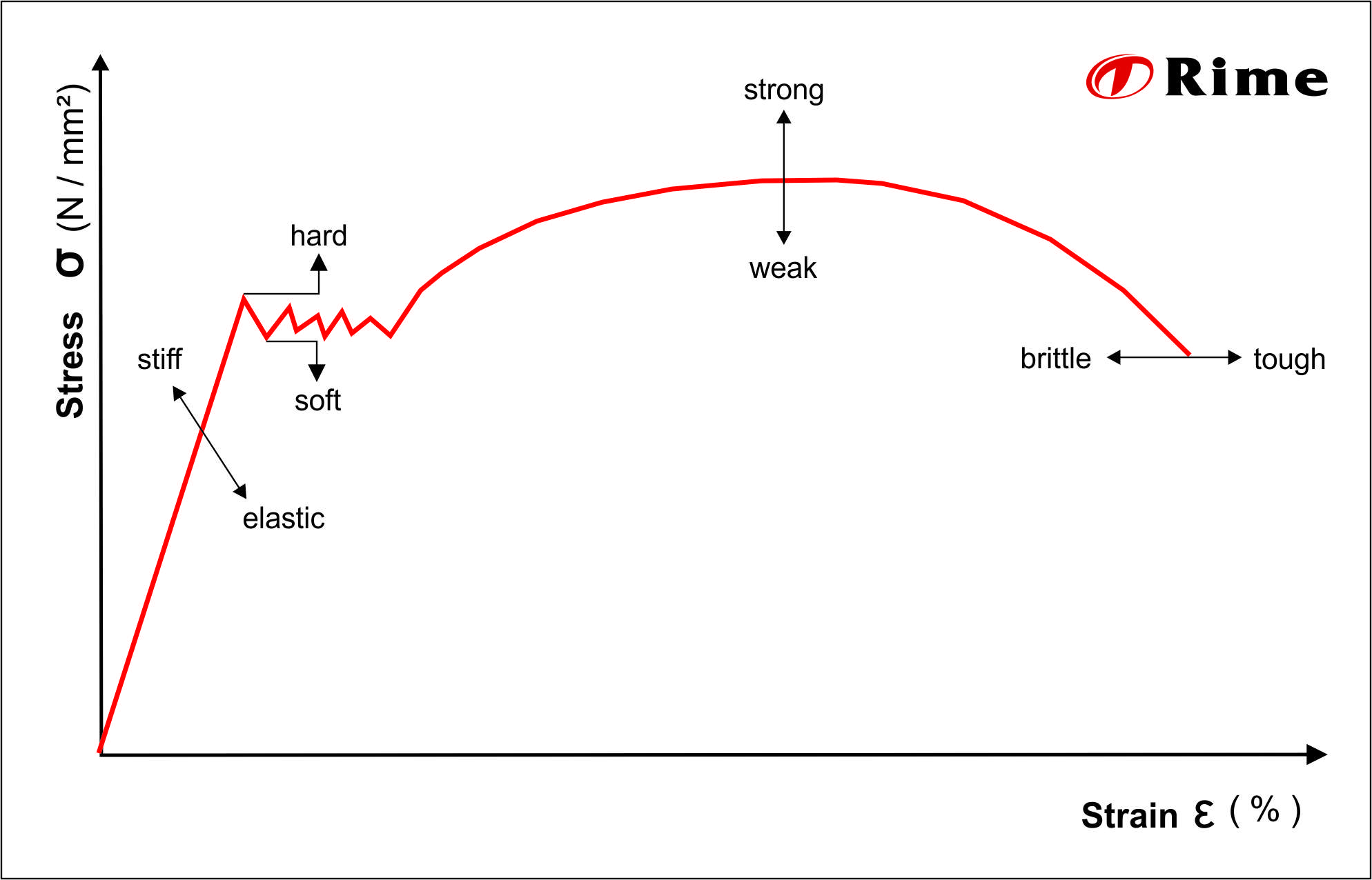
- stiff / elastic
In the elastic deformation area the graph is a straight line. The slope angle of this straight line can be used to deduce how stiff the material is. The steeper this line rises the stiffer the material. If the graph is shallower, the material is elastic. - hard / soft
The higher the limit at which the material begins to flow the harder the material is. Harder materials have the advantage that they can withstand far higher forces before they deform. This is especially important for load-bearing constructions. Soft materials on the other hand are easier to deform. - strong / weak
Strong materials can withstand far higher tensile forces. Weak materials form necking very quickly, even at low stress values, which means they also tend to tear more quickly. - brittle / tough
The last important property is the differentiation between brittle and tough materials. Brittle materials cannot withstand high tensile forces and break significantly faster. Tough materials also have the advantage that when overloaded they form marked deformations before they tear. This means that material fatigue is visible long before tearing, so that action can be taken in response.
See also
Brinell hardness test
Performing the hardness test by means of a ball pressure test according to the Swedish engineer Johann August Brinell.
Read moreCoil
Plate metal that is rolled-up to coils is easier to transport and requires less space in the warehouse
Read moreCorrosion
Corrosion is a natural process and damages most metals. What types of corrosion are there?
Read more